The Z-axis wobble problem is a common problem. A lot of people have this problem and it will have a big impact on our prints. This article will tell you the reasons for z-axis wobble and corresponding solutions.
Stepper Motor
First of all, we need to classify stepper motors.
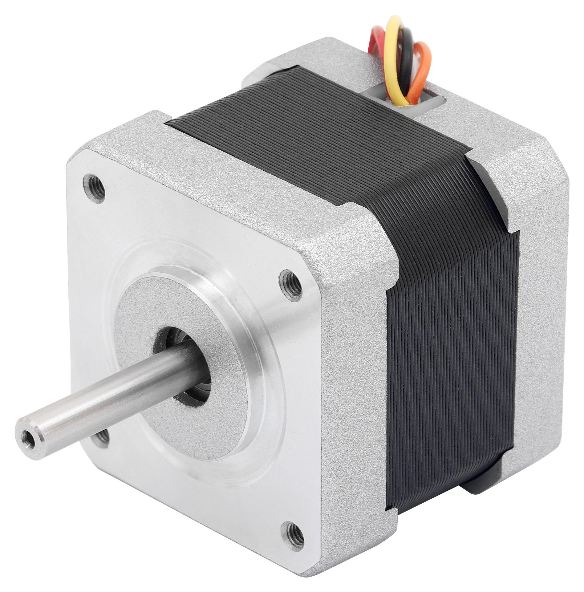
This is a standard stepper motor
This is a stepper motor with a lead screw
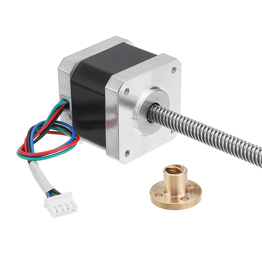
You can clearly find the difference between them. The shaft of the common stepper motor is very short and the shaft of the stepper motor with a lead screw is longer than the common stepper motor. The common stepper motors use couplers that can connect themselves and the lead screw together. So they can turn in sync.
A Stepper motor with a lead screw does not require a coupling because the screw is built from inside the stepper motor. No matter what type of stepper motor they are, they all need to use lead screw nuts to tighten them.
After we understand the basics, we try to analyze the Z-axis wobble caused by the stepper motor
The problem could be the coupling, the lead screw nut, and the lead screw itself.
1) The coupling is generally caused by you not tightening the grub screw, when your grub screw is loose, the rotation of the motor and the lead screw are not all synchronized. This will result in your Z axis of prints doesn't looks nice—another possibility: The hole inside the coupling is not completely straight. So we only need a simple adjustment or replacement to solve it.
2) Lead screw nut is generally due to the fact that you have tightened it too tightly. Generally speaking, we think that the screw needs to be tightened. This seems to be true in most cases. However, in this scene, it is not the best way, we recommend that you reserve some clearance properly, which can reduce the rigidity of the lead nut and lead screw connect. In addition, you should add the right amount of grease to it, which can reduce the noise when moving.
3) If the lead screw is bent then it will cause the move doesn't smooth. You just have to roll it for a few weeks after setting it on a flat table while checking it to get the answer.
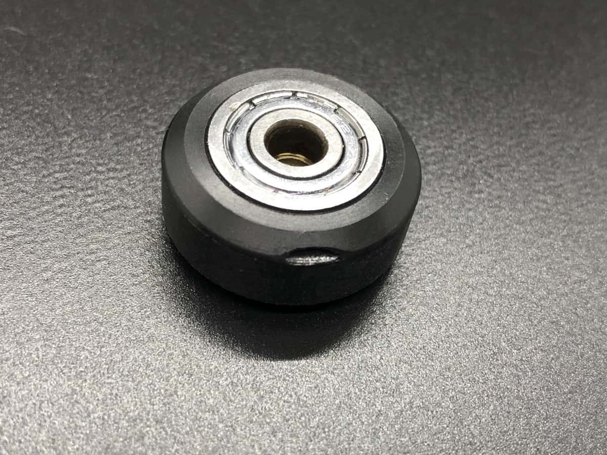
Wheel
Actually, I think there's a good chance that the cause of the Z-axis wobble is due to the scroll wheel. On a gantry printer, the rollers are generally distributed on the XYZ axis, that is say it's distributed among all the major moving parts. However, when we communicated with many users, they did not seem to care about the quality of the wheel and even appeared the problem, I checked a lot of things about the printer and finally found that it was a problem with the wheels.
How to check?
XY axis: First you need to unlock the motor (or in the off state) you can try to push the wheel, under normal circumstances, the push is smooth without obvious obstruction.
If you find that there is a partial stutter when turning, try loosening the roller fixing screw first, if the problem persists. Then there is a high probability that there is a problem with the scroll wheel, you can
Double-check by looking closer at the roller surface
Z axis: Unlike the XY axis, because we cannot push it easily, you can observe the surface of the roller to confirm whether the roller is damaged.
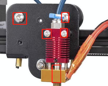
Hotend
Are you serious? Yes. When your hotend is not securely fastened, then your print surface will look similar to the Z-axis wobble. It's hard to tell the difference,
So you can check if the hotend is loose to circumvent this problem.
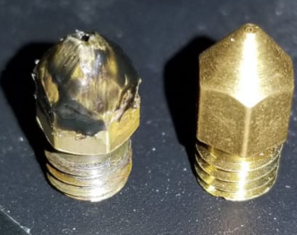
Nozzle
When you see a problem with one side of your print, while the rest is fine, chances are it's due to the nozzle. If the nozzle is defective, it is easy to show this problem. So we can solve this problem by changing the nozzle.
Extra Solutions
PID tuning for hotend and bed
PID tuning the hotend should reduce temperature variation in prints, which can prevent Z banding through inconsistent extrusion. PID tuning is the process of re-programming your printer’s method for heating the nozzle to make it more efficient and less subject to over-heating or under-heating.
PID tuning of the bed should reduce temperature variation in prints, which can prevent the bed surface level change caused by the print object affected by this effect.
About marlin PID
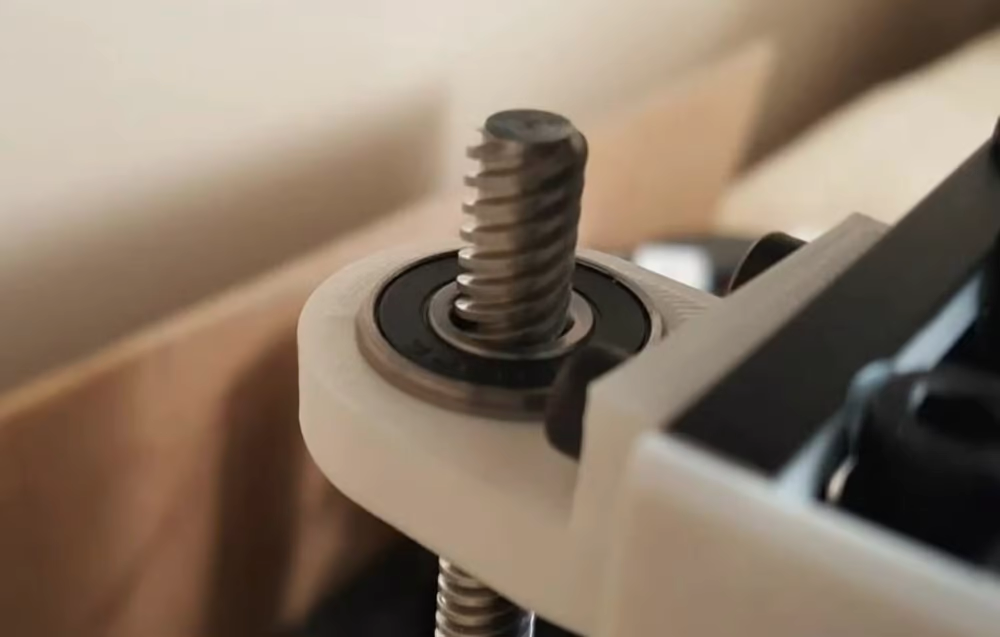
Stabilizer pieces
You can use an alignment or stabilizer part. This hardware aligns the top of the lead screw with the bottom by restraining the screw’s top position. Alignment pieces usually involve a bearing (where the inner hole goes around the rod) attached to a base that mounts to your printer’s frame. With a stabilizer part, you can adjust the top of the rod’s position to make sure that it’s centered with the bottom. You can purchase one of these online, like this injection-molded one, or you can 3D print one, such as this bearing fit model.